Golan Levin and Collaborators

Flong Blog + News

Computational Design Faculty Search at CMU

16 September 2010 / announcement, external, infovis, pedagogy

The School of Design at Carnegie Mellon University has announced a
Tenure-Track Faculty Search in Design and Computation,

for a position beginning August 2011:
http://www.design.cmu.edu/show_job.php?id=795

The Position
We are seeking a dynamic individual working in computational design to tackle global concerns, with experience in one or more of the following areas: information visualization and data mining, especially with very large and/or real-time data streams; experimental typography and interface design, with an emphasis on interactive software/hardware prototyping; interaction design for locative, mobile and/or wearable media; game design and other fields at the intersection of communication design and technology.

A candidate with a strong visual aesthetic, a trans-disciplinary orientation, conceptual rigor and contextual sensibilities is sought to teach 21st-century design skills and conduct innovative design research. We are looking for an individual who pushes current boundaries and explores new territories; thus the ability to forecast, identify and foster new areas of design research, experimentation and innovation is key. The position will involve collaboration with faculty in the School of Design as well as other departments across the University.

The ideal candidate is an expert in the application of algorithmic techniques to visual communication problems. Candidates should have demonstrable fluency in multiple programming environments for interactive visual prototyping, such as Processing, OpenFrameworks, Arduino, Jitter and/or ActionScript. A pedagogic orientation toward open-source methodologies and communities is especially welcome.

Qualifications
We seek a versatile designer with a significant record of professional practice, teaching, research publications, and/or public exhibitions. Candidates should have a master’s degree or equivalent practical experience. University-level teaching experience is desirable. Carnegie Mellon University is an Affirmative Action / Equal Opportunities employer committed to diversity.

Application to Include

  • Letter of application with teaching and practice philosophies
  • Curriculum Vitae
  • Documentation of work (see below)
  • Contact information, including phone numbers, for 3 references
    (No recommendation letters are required at this time)

Work Samples

  • Please provide a PDF containing up to 20 standard-size pages of visual and written documentation of your work. This PDF may also serve as a guide to additional online, interactive and/or video materials.
  • Provide the URL of your web site and your Twitter handle, if applicable. Sites will be viewed on Safari/Mac OSX with standard installations of Java and Flash. Include instructions for viewing select interactive projects, if applicable.
  • Up to 10 minutes of time-based work may be submitted on DVD-R, or in a web page with embedded video streams from e.g. Vimeo or YouTube.
  • Include samples of published research, if applicable.
  • Include a self-addressed stamped envelope for the return of your materials.

Email
Kristin Hughes, kh@cmu.edu

Or mail to:
Attn: Kristin Hughes
Design and Computation – Faculty Search
School of Design, MMCH-110
Carnegie Mellon University
5000 Forbes Avenue
Pittsburgh PA 15213-3890

Application Deadline:
06 December 2010 – or until position is filled.

The School
Carnegie Mellon’s School of Design is one of the oldest design programs in the United States, offering undergraduate, masters and PhD degrees in design. Located in one of the premier research universities in the world, the school is noted for its transdisciplinary masters degrees with the departments of English (Communication, Planning and Information Design) and Engineering (Masters in Product Development) and its BHA, BSA and BCSA undergraduate degree programs which enable students to design hybrid majors between Design and the humanities, natural sciences, and computer science.

At Carnegie Mellon University School of Design, we believe design is central to a better future. We employ design methods that synthesize traditional approaches with technological innovations to meet human needs. In 2009 the School began a re-visioning process that places “design for society and the environment” at the heart of the program, educating designers as transdisciplinary problem-solvers, and as catalysts for positive change. The School will launch several new master’s degrees as well as executive and continuing education programs over the next two years, providing several opportunities to expand its visionary and collaborative faculty.
Installing Arduino with Firmata for MaxMSP and Processing in OSX

8 July 2010 / code, external, reference

Firmata is a library which allows environments like Processing and MaxMSP/Jitter to communicate with the Arduino microcontroller over USB. More specifically, Firmata allows these environments to treat the tethered Arduino as a transparent interface board for communicating with sensors and actuators. This means that students learning MaxMSP or Processing can execute a reasonable subset of physical computing projects without ever having to program the Arduino itself (so long as their Arduino board has been programmed, once, with Firmata).

This blog post gives instructions for how to get Firmata working with both Processing and MaxMSP on Mac OSX 10.6.3. The information is current as of 8 July 2010, but is naturally certain to change. The context for this blog post is that I’m working with my university’s Computing Services staff to develop an administrator’s disk image for some new Macs that have just arrived. I prepared the information below for this crew, who are talented IT professionals that happen not to have domain expertise in arts-computing platforms. To the best of my knowledge, this information has not yet been compiled in any one place, but is rather distributed around the Internet in too many pages, some of which are out of date. I welcome comments and corrections.

————————————————————————————-

The specific list of 8 installation packages are as follows.
Detailed instructions for installing and testing these packages
can be found in the sections below.

  1. Arduino IDE version 0018: arduino-0018.dmg
  2. Drivers for Arduino boards: FTDIUSBSerialDriver_10_4_10_5_10_6
  3. Firmata version 2.1+ for Arduino: firmata.tar.gz
  4. Max/MSP/Jitter 5.1.3 or later: e.g. Max5_42462.dmg
  5. OSC-route external library for Max: OSC-route_1.17.1.tar.gz
  6. Maxuino library for Max v.009: maxuino-009.zip
  7. Processing version 0186, processing-0186.dmg.
  8. Arduino for Processing library, processing-arduino-0017.zip.
————————————————————————————-
Installing Arduino:

Overview of instructions below:

  • Install Arduino programming environment
  • Install FTDIUSBSerialDriver, a serial driver for Arduino boards
  • Install Firmata extension library for Arduino
  • Test Arduino installation

Installing the Arduino IDE:

Install the FTDIUSBSerialDriver v2.2.14:

  • This is a crucial serial driver for Arduino devices.
  • Make sure the Arduino app is not running.
  • Double-click on arduino-0018.dmg;
  • You will see a yellow package, FTDIUSBSerialDriver_10_4_10_5_10_6
  • Click on the package and follow the instructions.
  • You will need to enter the administrator password.
  • To check this installation, launch the Arduino app;
  • From the menu bar, navigate: Tools->Board->…
  • You should see a list of about a dozen different Arduino boards.

Installing the best version of the Firmata (2.1+) library for Arduino:

  • Make sure the Arduino app is not running.
  • In Applications, Right-click on the Arduino app, “Show Package Contents”
  • Navigate to (Arduino)/Contents/Resources/Java/libraries
  • You will see a library entitled “Firmata”. We want to replace this, so delete it or move it somewhere else.
    (Note: this replacement will not be necessary in Arduino-019 and later versions)
  • Download http://maxuino.org/wp-content/uploads/2010/02/firmata.tar.gz.
  • Replace the “Firmata” library included with Arduino-018 with this downloaded version.
  • Note: this downloaded version has the same release number (2.1) but is improved.
  • To check this installation, launch the Arduino app;
  • From the menu bar, navigate: Sketch->Import Library->Firmata
  • In the text area of the sketch, you should see two lines:
    #include <Boards.h>
    #include <Firmata.h>

Testing the installation of the Arduino IDE:

  • Obtain an Arduino Duemilanove board and USB cable.
  • Connect the Arduino board to a USB port.
  • Launch the Arduino app.
  • Open the “Blink” example:
  • Navigate from the menu bar: File->Examples->Digital->Blink
  • Choose the appropriate board:
    Navigate the menu: Tools->Board->”Arduino Duemilanove or Nano w/ ATmega328″
  • Guess and select the serial port on which the Arduino board is connected:
    Navigate the menu: Tools->Serial Port->/dev/tty.usbserial…
    (Note: you may need to test several different serial ports…)
  • Navigate: Sketch->Verify/Compile
  • Navigate: File->Upload to I/O Board
  • The Arduino board should twinkle briefly;
    then it should Blink on/off once per second.

————————————————————————————-
Installing Max/MSP/Jitter with Firmata:

Overview of instructions below:

  • Install MaxMSP/Jitter
  • Install OSC-route “external” for MaxMSP
  • Install Maxuino library

Install MaxMSP/Jitter:

Installing OSC-route, an external for MaxMSP

Installing Maxuino, a library for MaxMSP:

  • From: http://www.maxuino.org/?p=58
  • Download: http://www.maxuino.org/wp-content/uploads/2010/04/maxuino-009.zip
  • Unzip maxuino-009.zip
  • Drag the unzipped folder maxuino-009 into the Applications/Max5/ application folder, at the same level as the “Cycling ’74” folder, etc.
  • Launch the MaxMSP app.
  • Now we will add Maxuino to the MaxMSP Search Path:
  • Navigate the menu bar in MaxMSP: Options->File Preferences…->
  • Click the + sign at the bottom left of the File Preferences window; this adds a new path.
  • Press the “Choose” button and select the maxuino-009 folder.
  • Make sure the checkbox in the Subfolders column is checked.
  • Double-click on the “userpath_3” name, and change it to “Maxuino”
  • Close the File Preferences window and quit the MaxMSP app.
  • Instructions for testing the Firmata bridge to MaxMSP are below.

————————————————————————————-
Testing the Firmata bridge from MaxMSP to Arduino

First, in Arduino:

  • We assume you have installed and tested the Arduino IDE as described above.
  • With the Arduino board connected to a USB port, launch the Arduino app.
  • Check that the board type is correct: Tools->Board->”Arduino Duemilanove or Nano w/ ATmega328″
  • Check that the USB port is correct: : Tools->Serial Port->/dev/tty.usbserial…
  • Open the example program, File->Examples->Firmata->StandardFirmata
  • Navigate: Sketch->Verify/Compile
  • Navigate: File->Upload to I/O Board
  • The Arduino board should twinkle briefly….

Then, in MaxMSP:

  • Double-click “MaxMSP” to launch the application.
  • Navigate the menu bar in Max/MSP: File->Open….
  • Open the Max patch file:
    Applications/Max5/maxuino-009/examples/maxuino-example-GUI.maxpat
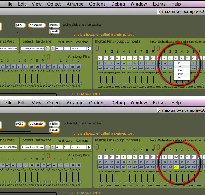
  • For the next instructions, please refer to the attached image, “max-test-firmata.png”
  • You will see a dark green window, with a light green section called “Digital Pins”
    on the right half of the screen, with pins numbered from 0…53.

  • In this section, find Pin 13, which is under the “3” to the right of the large “10”.
  • Click on the little white box which says “in”; this will reveal a small pulldown menu.
  • Using this menu, set Pin 13 to become an output instead of an input.
  • Now click the gray button labeled “out” which is two buttons below the white button.
  • The button will turn yellow and report “OUT” in all-caps;
    Meanwhile, the orange LED on the Arduino will light up.
  • Clicking on the “OUT” button once again will turn off the Arduino’s LED.

Possibly helpful additional web pages:
http://www.cycling74.com/docs/max5/vignettes/core/file_preferences_window.html#searchpath
http://www.soundplusdesign.com/?p=1305
http://www.maxuino.org/?p=58

————————————————————————————-
Installing Processing with Firmata:

Overview of instructions below:

  • Install Processing development environment
  • Install Arduino for Processing extension library
  • Check that the library is installed.

Install “Processing” version 0186:

Instructions for installing “Arduino for Processing” Library:

  • After installing the Processing app in the Applications directory,
  • Make sure the Processing app is not running.
  • From: http://www.arduino.cc/playground/Interfacing/Processing
  • Download: http://www.arduino.cc/playground/uploads/Interfacing/processing-arduino-0017.zip
  • Right-click on the Processing app, to “Show Package Contents”
  • Navigate to (Processing)/Contents/Resources/Java/libraries
  • Unzip “processing-arduino-0017.zip”, which produces a folder called “arduino”
  • Drag the “arduino” folder into the “libraries” folder. It will be at the same level as “dxf”, etc.
  • Now we will put the “Arduino examples” in the correct place:
  • Create a new folder in (Processing)/Contents/Resources/Java/examples/Library/ called “Arduino”.
    You should now have: (Processing)/Contents/Resources/Java/examples/Library/Arduino
  • Open (Processing)/Contents/Resources/Java/libraries/arduino/examples
    You will see 3 folders, for “arduino_input”, “arduino_output”, “arduino_pwm”
  • Drag these 3 folders into (Processing)/Contents/Resources/Java/examples/Library/Arduino.
  • To check this library installation:
  • Double-click “Processing” to launch the application.
  • In the menu bar, navigate to Sketch->Import Library….
  • In the resulting pulldown menu, you should now see: arduino among the other libraries.
  • Navigate the menu bar: File->Examples->Library->Arduino
  • You should see “arduino_input”, “arduino_output”, “arduino_pwm”.
  • Instructions for testing the Firmata bridge to Processing are below.

————————————————————————————-
Testing the Firmata bridge from Processing to Arduino

First, in Arduino:

  • We assume you have installed and tested the Arduino IDE as described above.
  • With the Arduino board connected to a USB port, launch the Arduino app.
  • Check that the board type is correct: Tools->Board->”Arduino Duemilanove or Nano w/ ATmega328″
  • Check that the USB port is correct: : Tools->Serial Port->/dev/tty.usbserial…
  • Open the example program, File->Examples->Firmata->StandardFirmata
  • Navigate: Sketch->Verify/Compile
  • Navigate: File->Upload to I/O Board
  • The Arduino board should twinkle briefly….

Then, in Processing:

  • Double-click “Processing” to launch the application.
  • Navigate the menu bar: File->Examples->Library->Arduino
    You should see “arduino_input”, “arduino_output”, “arduino_pwm”.
  • Open the example project “arduino_output”.
  • Navigate the menu bar: Sketch->Run
    You will see a small blue window with 14 boxes.
  • Click the leftmost box while observing the Arduino board.
    The Arduino’s LED should light up.
  • Click the leftmost box again.
    The Arduino’s LED should turn off.


GML Stenciler: Laser Cut Patterns from Graffiti Markup Language

3 July 2010 / announcement, code, project

We announce the release of GMLStenciler, an open-source software project for converting Graffiti Markup Language (GML) drawings into vector-art stencils suitable for laser cutting. This free tool solves the problem of transforming GML’s widthless linear strokes into adjustably-thickened stencil patterns with automatically bridged islands. GMLStenciler is built in openFrameworks, an open-source C++ toolkit 
for creative coding; it can be downloaded below (with complete source code) for Windows and Mac OSX.

Overview
In January 2010 the F.A.T. Lab released a suite of XML specifications and open-source tools for recording and displaying handwritten marks, which they named Graffiti Markup Language (GML). Their flagship system is the Graffiti Analysis software by Chris Sugrue and Evan Roth, which allows GML drawings to be recorded with an iPhone, uploaded to an online database, and freely shared at the #000000book.com website. Users of Graffiti Analysis have contributed some 17,500 tags to date. As with our Robotagger project, the GMLStenciler software presented here offers a means by which these virtual handwritten marks can be given physical form, made multiple, and economically disseminated at a variety of scales.

Operation
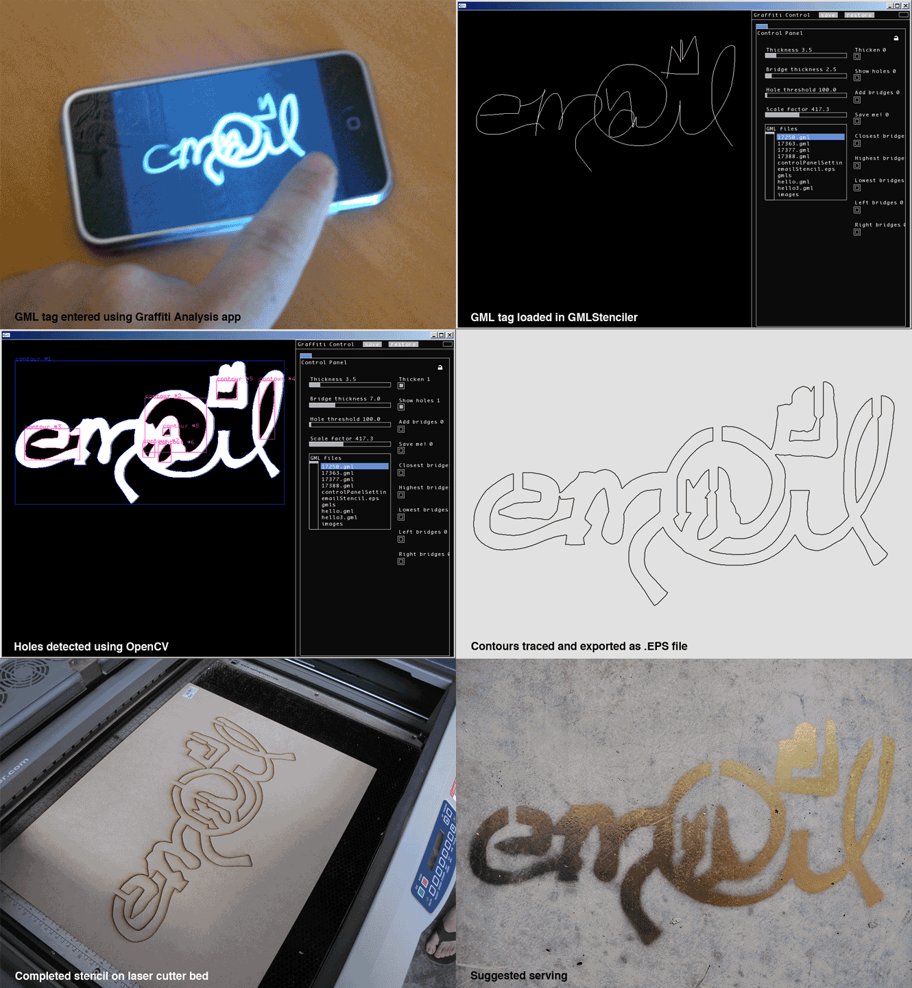
The Graffiti Markup Language specification defines a “tag” as a sequence of linear “strokes”, each consisting of a sequence of timestamped (x,y) points. These strokes lack a width or thickness; as a result, it is not possible to stencil raw GML tags directly. GMLStenciler solves this by providing a tool in which:

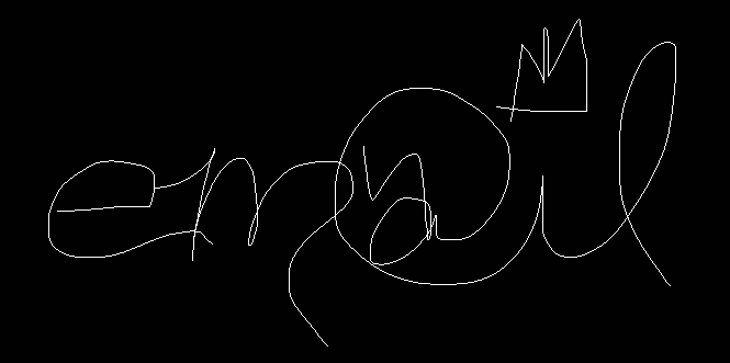
● The user imports a GML file, such as this one from 000000book.com:

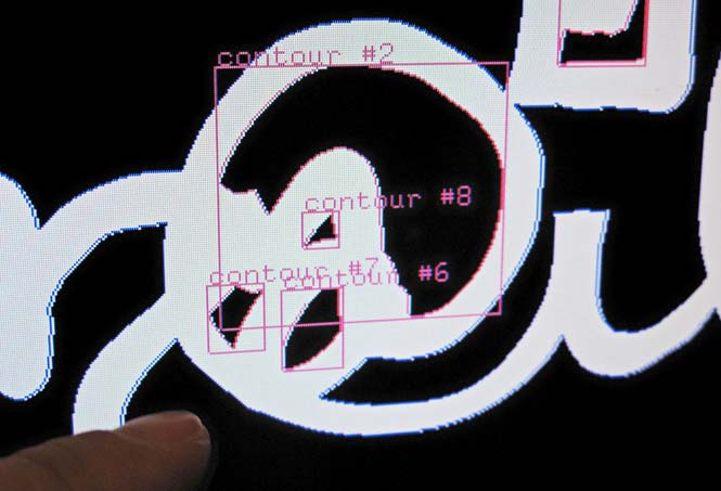
● An interface is provided by which the user can select an adjustable thickness for rendering the tag’s strokes. Using OpenCV, the system then automatically detects “holes” in the rendered tag (such as would be produced by the closed counters within characters like A, B, D, O, P, Q, R, etc.). These holes are problematic for stencils because they form loose “islands” that, left unbridged, would disappear from the final stenciled design.

The software automatically detects 'holes'

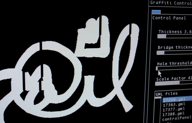
● The user can select one of several methods by which these holes will be automatically bridged. Options for this operation include: bridging at the top point of each counter, bridging at the nearest point to the counter’s enclosing stroke, etc. Because GMLStenciler bridges holes recursively, strokes with complex nested structures or holes-inside-of-holes (as in the symbols ®, ◎, ©, ʘ, etc.) are still bridged successfully:

The software automatically bridges islands in the stencil

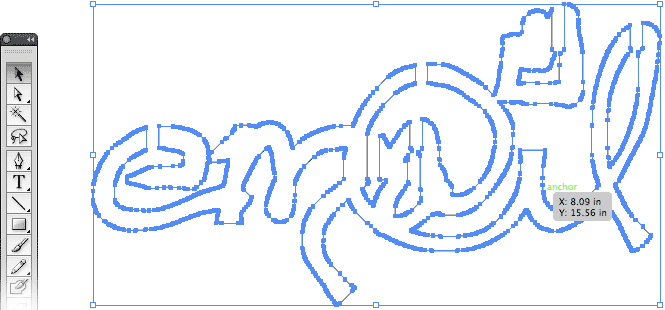
● The user can export the stencil design as an EPS (Encapsulated PostScript) vector file. (Here’s a raw example output file created by GMLStenciler.) Optionally, this EPS file can be loaded into CAD programs or vector art editors like Illustrator or CorelDraw for further editing:

EPS files generated by GMLStenciler can be opened in common vector editors.

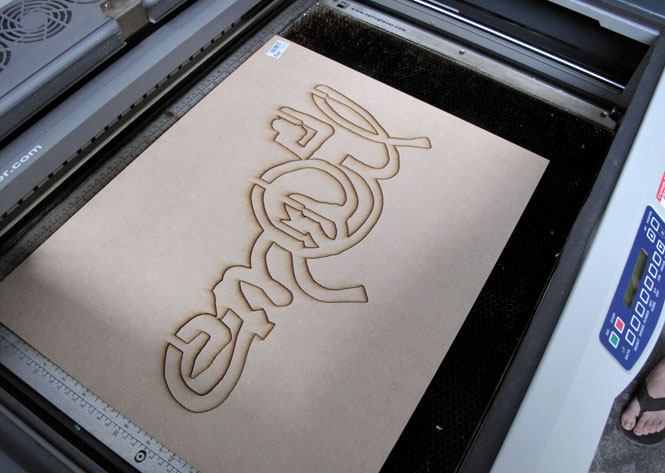
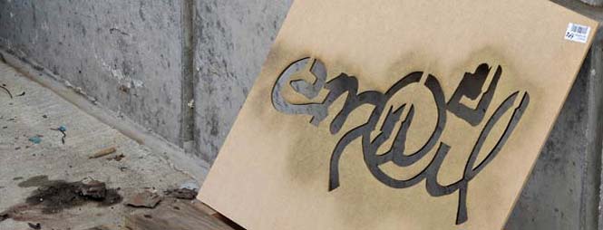
● The EPS file can then be used as the pattern for cutting a stencil on a laser cutter, vinyl cutter, water-jet cutter, CNC router, or other computer-controlled cutting machine. Laser cutting services are widely available in many cities, and are also increasingly common in regional hacker spaces and university art, architecture and design departments. Below, the stencil has just been cut from 1/8″ MDF (20″x16″, about $3) on a 40-watt Epilog laser cutter; cutting time was under 2 minutes. For very large stencils, I recommend using a CNC router, many of which can accommodate materials up to 5’x10′.

Stencils generated by the software can be cut on a laser-cutter.

These stencils can then be used in a variety of ways. One interesting potential use for such stencils is so-called cleanfitti or reverse graffiti (also known as clean tagging, dust tagging, or grime writing), in which the stencil is used as a frisket for dirt removal.

Downloads

The GMLStenciler can be downloaded here:

  • GMLStenciler_1.00_mac.zip [20MB] Includes app and source, as an openFrameworks v0.061 project for MacOSX 10.6.3 / XCode. This zip includes all necessary (ofx) addons, but developers wishing to recompile this will still need to download the openFrameworks v0.061 library. This slimmer 11MB zip omits standard ofx addons and assumes you already have OF v0.061 working.
  • GMLStenciler_0.99_win.zip [21MB] Includes exe and source, as an openFrameworks v0.061 project for WinXP+ with MS VisualStudio 2008. This build currently lags the Mac version very slightly.
  • As a Github repository. Developers, note: The most recent version of the source code can be found here.

License and Disclaimer
The GMLStenciler software is licensed under the CC-GNU GPL version 2.0 or later. All Graffiti Analysis related media is licensed under a Creative Commons Attribution-Noncommercial-Share Alike 3.0 United States License. Users of GMLStenciler are solely responsible for their activities while using this tool; this site and its author(s) do not condone illegal uses of the GMLStenciler software.

CC-GNU GPL

Creative Commons License

Credits and Acknowledgments
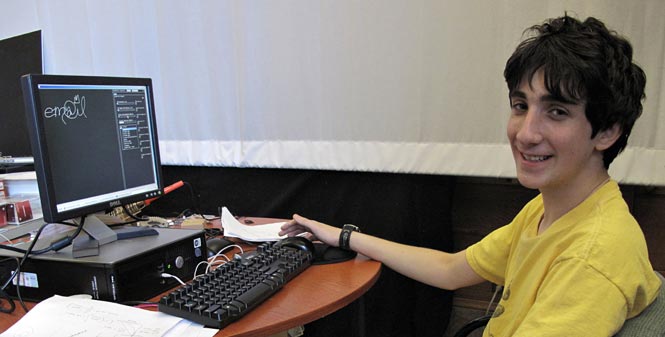
The GMLStenciler software was entirely developed by Charlie, my 15-year-old intern, during June 2010. Charlie (a rising Junior in a Pittsburgh-area high school) has a solid background in Java programming and server-side web scripting, but hadn’t previously worked with C++, OpenGL, OpenCV, or openFrameworks, so this proved to be an ideal learning project. Here’s a photo of Charlie.

Charlie developed GMLStenciler in openFrameworks under the auspices of Golan Levin. GMLStenciler makes use of the Graffiti Markup Language (GML) specification released by the F.A.T. Lab, and includes code developed by Chris Sugrue and Evan Roth for their Graffiti Analysis software. The GMLStenciler also uses the OpenCV open-source computer vision library. Thanks to Kyle McDonald, Jacob Tonski and Solomon Bisker for supporting Charlie with ad hoc coding advice during his internship. Thanks to the STUDIO for Creative Inquiry at Carnegie Mellon University for hosting Charlie, and to the CMU School of Art for the use of its laser cutter. GML “em@il” tag by Evan Roth. Documentation photos by Kyle McDonald.

References

Keywords
FAT, GML, GRL, #OF, Free Art and Technology, Graffiti Markup Language, openFrameworks, graffiti research, GML-Stenciler, GMLStenciler, GML-Stenciller, GMLStenciller, free open-source software, source code, software tools, app, laser cutting, laser cutter, rapid prototyping, digital manufacture, pochoir, frisket, stencil, stenciller, stenciler, cut patterns, vector art, vector output, XML, EPS, PDF, CAD, C++, OpenCV, graf, graffiti, grafitti, cleanffiti, cleanfitti, inverse graffiti, reverse graffiti, clean tagging, dust tagging, grime writing, computational design, computer-aided stenciling, automatic stencil creation, automatic stencil generation, hacking, Robotagger, graffiti and automation.


Rectified Flowers

29 June 2010 / code, project

Kyle McDonald and I were reading about domain shifting between polar and Cartesian geometries, and noticed that flowers make particularly interesting subjects for this transformation. Abusing my open-source BloggieUnwarper panoramic-imaging software with some flower photographs from Flickr, we produced the “flower panoramas” below. This is what you would see if you were doing panoramic imaging from inside a flower

A complete set of about two dozen such panoramas can be seen in this Flickr set.

A modified version of the software — the FlowerUnwarper — was optimized for unwarping flower images, and is available here (including source code). The software is built in Processing and uses the ControlP5 library. All of the source photos used in this project were distributed with Creative Commons Attribution licenses. Our software is free in the Public Domain and our own re-processed images are released under the Creative Commons Attribution-ShareAlike 3.0 Unported License.

Update (July 10): The folks at NotCot have since used our software to create these fascinating views of unwarped chandeliers!

Keywords: polar to cartesian, flowers, warping, unwarping, unwrapping, dewarping, rectification, inverse warping, correction, panorama, macro, macrophotography, Processing, surrealism, flower landscapes, petals, Processing, Java, free source code, free software, polar transformation of flowers.


Modding the Bloggie Panoramic Lens Accessory

26 June 2010 / project

This post explains how to achieve full 1080p video with the Sony Bloggie’s 360-degree video accessory. It also illustrates some of the limitations you will encounter in doing so.

In my previous blog post about panoramic imaging with the Bloggie, I complained about how the Bloggie automatically lowers its resolution from 1920×1080 down to 1280×720 when the panoramic lens accessory is fitted onto the camera. Happily, Jan Martin from DIY-streetview.org helpfully pointed me to this short post by onezebra1 on the PanoTools discussion board, which describes how to modify the accessory to support full-resolution video recording with the Bloggie. As we had suspected, the Bloggie uses a magnet to trip the resolution switch. Removing this magnet is easy, and produces the desired result — annular panoramic video at the device’s highest possible resolution — with some caveats.

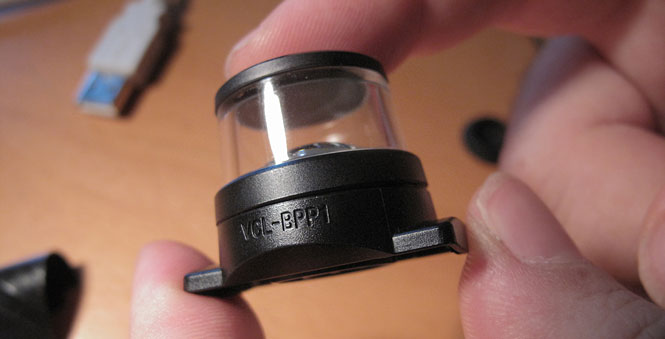
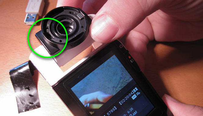
Here’s the Bloggie’s panoramic lens accessory, Sony Part Number X25467051, labeled VCL-BPP1 on its body. On the underside of the accessory are 4 very small cross-head screws (not pictured):

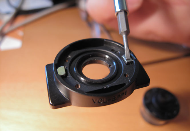
Removing these four screws allows the optics to be separated from the mounting base. Once separated, you will find two small rare-earth magnets inset into the the inner (upper) surface of the base. These magnets (each about 3x4mm) can be extracted with a small flat screwdriver. The photo below shows the inner surface of the base. At the bottom right of the photo is the optics half of the assembly.

It turns out that only the left magnet needs to be removed for the hack to work. I recommend doing this to preserve maximum flexibility for your optics.

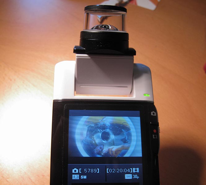
The optics are reassembled and fit onto the camera as before, and voilà — panoramic video at 1080p resolution on the Bloggie:

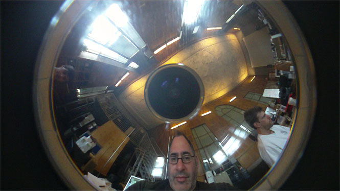
There is, however, an important caveat. The panoramic donut is now truncated on the top and bottom, as you can see above. Here is a still frame from the 1920×1080 video recorded in this way.

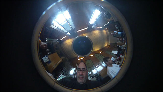
For comparison, below is a still from a video recorded in 1280×720 resolution; as you can see, the entire donut is visible. I had left one of the magnets installed, so I just flipped the same lens around to produce this. But it’s also possible to recover the Bloggie’s factory-standard 720p panoramic video behavior by selecting 1280×720 resolution from its menu system.

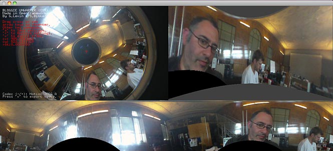
Using the 1080p-resolution annular videos with my BloggieUnwarper software is straightforward. (The MAXR_FACTOR and MINR_FACTOR properties must be set to approximately 1.2648 and 0.3018, respectively.) Below is a screenshot, which shows how the truncated regions are interpreted by the rectification process. For what it’s worth, these missing regions account for 6.8% of the area of the unwarped panorama.

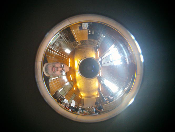
By the way, it’s worth clarifying that the Bloggie’s still images remain unaffected by this modification; the operation described above only affects the camera’s video recording capabilities. Below is a panoramic still shot at the Bloggie’s highest resolution (2592×1944). The annulus has the same dimensions as the 1920x1o80 video, but without the cropping. Both unmodified and modified optics will produce such still images on the Bloggie. The image quality is much clearer, probably because of a longer exposure time and different compression configurations.

After making some more careful measurements, I’ve determined that the maximum vertical resolution obtainable from the Bloggie’s standard 1280×720 video is ~261 pixels, while the maximum obtainable from the 1920×1080 video is ~518 pixels. So it may be worth making the mod, if you can tolerate missing about 6.8% of your pixels in a couple of places. [Photography: Kyle McDonald]